#include"xspi.h" // axi quad spi#include"xparameters.h"#include"xstatus.h"#include"xplatform_info.h"#include"xil_printf.h"#include"sleep.h"#define SPI_DEVICE_ID XPAR_SPI_0_DEVICE_ID
#define SPI_BASEADDR XPAR_SPI_0_BASEADDR
XSpiSpi;intmain(){/*
* SPI Initialize
*/XSpi_Config*spi_config_ptr;spi_config_ptr=XSpi_LookupConfig(SPI_DEVICE_ID);if(spi_config_ptr==NULL){returnXST_DEVICE_NOT_FOUND;}status=XSpi_CfgInitialize(&Spi,spi_config_ptr,spi_config_ptr->BaseAddress);if(status!=XST_SUCCESS){returnXST_FAILURE;}// Start the SPI driver so that the device is enabled.
XSpi_Start(&Spi);// Disable Global interrupt to use polled mode operation
XSpi_IntrGlobalDisable(&Spi);/*
* 1. Enable master mode.
* 2. CPHA = 1, CPOL = 0
* 3. Manual Slave Select
* 4. TX/RX FIFO Reset
*/u32control;control=XSpi_ReadReg(SPI_BASEADDR,XSP_CR_OFFSET);control|=XSP_CR_MASTER_MODE_MASK|// Master Mode
XSP_CR_CLK_PHASE_MASK|// Clock Phase
XSP_CR_MANUAL_SS_MASK|// Manual Slave Select
XSP_CR_TXFIFO_RESET_MASK|// TX FIFO Reset
XSP_CR_RXFIFO_RESET_MASK// RX FIFO Reset
;XSpi_WriteReg(SPI_BASEADDR,XSP_CR_OFFSET,control);// write [0x00 0x37] and then read one byte
XSpi_WriteReg(SPI_BASEADDR,XSP_DTR_OFFSET,0x00);XSpi_WriteReg(SPI_BASEADDR,XSP_DTR_OFFSET,0x37);XSpi_WriteReg(SPI_BASEADDR,XSP_DTR_OFFSET,0x00);/*
* SPI write
*/XSpi_WriteReg(SPI_BASEADDR,XSP_SSR_OFFSET,0xE);// slave select // 0xE: 0b1110
// initiate a transfer
control=XSpi_ReadReg(SPI_BASEADDR,XSP_CR_OFFSET);control|=XSP_CR_ENABLE_MASK;control&=~XSP_CR_TRANS_INHIBIT_MASK;XSpi_WriteReg(SPI_BASEADDR,XSP_CR_OFFSET,control);/*
* SPI read
*/// wait for the transmit FIFO to be empty
while(!(XSpi_ReadReg(SPI_BASEADDR,XSP_SR_OFFSET)&XSP_SR_TX_EMPTY_MASK));control=XSpi_ReadReg(SPI_BASEADDR,XSP_CR_OFFSET);control|=XSP_CR_TRANS_INHIBIT_MASK;XSpi_WriteReg(SPI_BASEADDR,XSP_CR_OFFSET,control);// read data receive register
while((XSpi_ReadReg(SPI_BASEADDR,XSP_SR_OFFSET)&XSP_SR_RX_EMPTY_MASK)==0){data=XSpi_ReadReg(SPI_BASEADDR,XSP_DRR_OFFSET);}// we know (in advance) that the slave will return one byte, so we know this loop will be executed three times.
// slave de-select
XSpi_WriteReg(SPI_BASEADDR,XSP_SSR_OFFSET,0xF);// 0xF: 0b1111
xil_printf("MISO: 0x%x\n\r",data);return0;}
4 Linux 编程
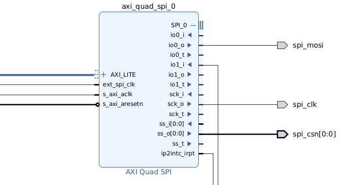
为了在 Linux 中使用 AXI Quad SPI IP 核,需要在 Linux 设备树中添加一个 spidev 节点,从而允许通过读写 /dev/spidevx.y 文件来读写 SPI。
在 /dev/spidevx.y 中,x 代表第 x 个 SPI 控制器,y 代表第 y 个片选。如果使用 PS SPI,那么设备名可能为 /dev/spidev0.0;如果使用 PL SPI(AXI SPI),则设备名可能为 /dev/spidev1.0。
设备树通常在启动时被 U-Boot 加载好,并且不可修改。但是 4.14 版本之后的 Linux 内核增加了对 device tree overlay(以下简称 DTO)的支持。DTO 允许在运行时动态加载新的设备树。下面是一段 DTO 的源码: